LCD systems
Interior LCD display design for passengers
Indoor LCDs of various designs are intended for use inside public transport vehicles, where they can perform various functions, i.e. from passenger information to control terminals (they are supplemented by a touch screen).
The design is thus as follows:
- as mere video signal displays (so-called SLAVE mode) - i.e. they receive the video image either directly from the on-board computer (e.g. our EPIS 5A KS) or from another superior LCD - the MASTER-SLAVE system. The master system copies the video signal for the dependent LCDs from the signal generated by them (see all-in-one system),
- as an all-in-one system (so-called standard design) - i.e. the LCD display contains an internal control PC in front, double-sided or side (wide-angle) design. It can be in MASTER function,
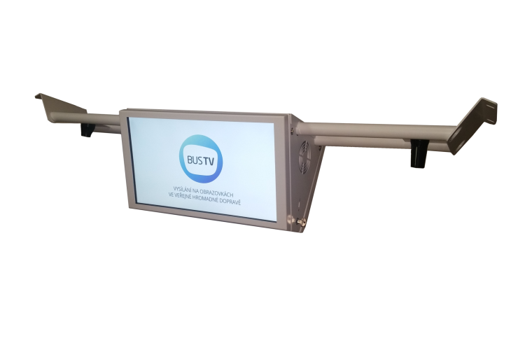
- as a communication advertising LCD with the possibility to display traffic information. This unit can incorporate both a UCU communication unit or EPG modem, as well as implement WiFi for vehicle passengers at the same time.
- As a central unit of the camera systems, where the unit also contains a recording disc to which the video streams from the vehicle cameras are recorded, while displaying the events from the selected cameras.
- LCD touch control terminals for the operator or driver, whereby the touch pad is used to send press point data to the parent unit. These are industrial replacements for classic touch LCD monitors adapted for industrial operation and for operation in public transport vehicles or trains and controlled from PCs or similar devices generating video signals. They can also be used as part of an information kiosk at bus stops.
Methods of controlling in-vehicle LCDs
LCD control modes (stand-alone, from on-board computer, remotely controlled by a supervisory server)
In-vehicle passenger LCD panels have three basic control schemes for which the appropriate software application must always be loaded in the LCD to ensure the desired behaviour. These are the following control modes of the in-vehicle LCD:
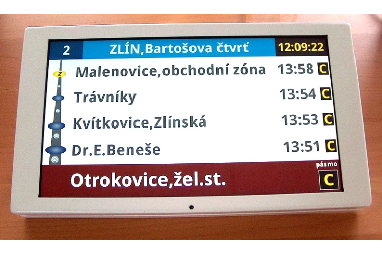
1. Autonomous (simplest), where the LCD listens to information on the IBIS bus (most often), which is usually supplemented with information about stops along the vehicle route and these are displayed sequentially. For this purpose, the LCD must have a PC control unit that provides this function - LCD STANDARD. The LCD must have the appropriate control software, which may be different in each region or carrier. This method is now being abandoned.
Display of the vehicle route on the LCD for passengers when collecting data from the IBIS bus.
2. Controlled from the on-board computer, i.e. a situation where the LCD receives much more information to display the data, or can display additional traffic information and advertising that has been uploaded in the carrier's vehicle. Recording can be done remotely using our RADON system or from the Backoffice BOS. The connection via the Ethernet bus in the vehicle is a prerequisite. For control we now offer the EPIS-NET protocol.
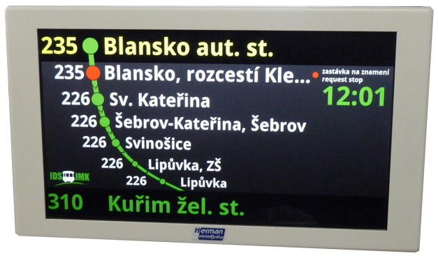
Example of controlling LCD type VCS 185 using EPIS-NET protocol in IDS JMK.
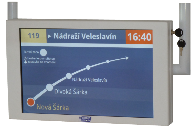
3. Systems with remote control of internal LCDs for passengers - here there are several different ways of control, either by updating information about vehicle departures from the next stop (for the first time in the Czech Republic) - see. "Dynamic Vehicle Marker" or including projection and updating of advertisements in the vehicles, which are part of the offer of our systems. To work correctly, a vehicle - public transport control room or IDS - advertising management server connection is required.
4. Autonomous advertising-only system - which may or may not be connected to vehicle IT and is controlled remotely from the traffic information, news and advertising server (in preparation). This LCD incorporates an all-in-one solution complete with a fast GSM modem and GSM antenna. It only needs to be connected directly to the +24V power supply of the bus and all other information is "downloaded" from the server (e.g. VCS 215 Bx-LW).
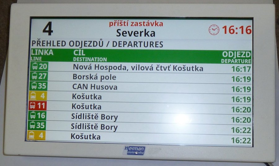
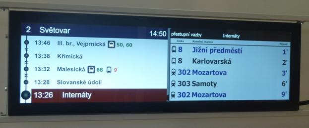
Example of display of current departures in the vehicle from the current stop (Severka) obtained from the control room according to point 3 of the control methods.
5. Operation as a touch LCD monitor - this is a control LCD monitor with a capacitive touch surface replacing standard touch LCD monitors, but in the "antivandal" version. It is directly connected to the video output of the control computer (usually a PC).
Communication bus for internal LCD
Indoor LCD panels can be controlled using all types of buses (Ethernet, RS 485, IBIS or according to our definition of fast IBIS):
- The IBIS bus is only suitable for stand-alone operation of the passenger LCD and does not allow for further system development. When using this bus (1200 bit/s with 7-bit alphabet) or our fast IBIS solution (up to 19200 bit/s with 8-bit alphabet), the indoor LCD essentially replaces the indoor LED panel, e.g. VLP 20×120. In case of using slower bus types (IBIS or RS 485), the possibility of very easy playback of the panel content using a USB flash drive (automatic update in a few seconds) can be used with advantage. The reason for the playback is if the system allows the playback of advertisements or traffic information.
- For the solutions we supply, we prefer a communication bus with an Ethernet-type master unit (see the article "New vehicle concept" or "Dynamic Vehicle Marker"), as this allows remote updating of data, traffic information, advertising spots and LCD SW. The system can therefore be further developed and easily maintained.
MASTER - SLAVE version
As already mentioned, the LCDs supplied by us can be supplied separately or in MASTER-SLAVE version. The MASTER-SLAVE version has the advantage that both LCDs display identical screens or videos. In this case, the video signal is "separated" in the control LCD called MASTER, which is routed to the second LCD called SLAVE and displayed there. The connection is made with a UTP cable at least cat. 6 with a maximum length of 15 m and with a resolution of up to "full HD" (1920 x 1080 pixels). The cable is also used to control the slave unit so that the backlight of the LCD display can be controlled, e.g. on the final ones.
MASTER/SLAVE connection for LCD for passengers in public transport vehicles.
A first LCD and a second LCD are produced:
- single-sided version - single-sided version
- double-sided version - single-sided version
- double-sided version - double-sided version
Parent units and systems
The parent unit local to the vehicle is the on-board control unit (OBU) or remote dispatch server or ad server. The parent unit in the vehicle is:
- On-board computer for public transport - e.g. our on-board computer for public transport - EPIS 4.0x,
- On-board computer with check-in (so-called machine or cash register) for public line transport - e.g. our EPIS 5 FC,
- the compact on-board computer MSP 5.0.
For systems that are to enable remote control of the display on LCD panels (from the public transport control room or from the advertising server or the traffic information and daily news server), we offer 3 solution options always based on data transmissions via GSM/GPRS/UMTS (LTE system is under development):
- For public transport vehicles, remote control via the new GSM EPG 4.0 unit, complementing the features of the EPIS 4.0x on-board computer.
- For public transport vehicles, the EPIS 5 FC on-board computer with check-in, which has the required modem integrated,
- for public transport vehicles, supplemented by the MSP 5.0 position tracking unit. This unit, by having a fast GSM modem, allows remote control and data updating in the internal LCD vehicle panel.
The automatic remote data update can be done e.g. by using our on-board computers of the EPIS 4.0x series and the RADON vehicle management software (part of the SPRINTER software). In this case there is no need to update the data manually.
Vehicle LCD panel display cycles controlled from the on-board computer
The layout of the individual windows can be changed by the user in the CityScreenInfo compiler and there is no need to create manually difficult to define *.BAT files. Advertising or traffic announcements, e.g. a message from a dispatcher, can be included in the cycles when travel time permits.
Next stop - permanent.
The on-board LCD panels for public transport passengers can, for example, operate in the following cycles:
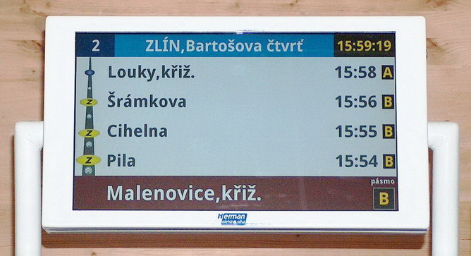
- The next stop "permanent" is displayed when driving to the next stop. The next stop is displayed at the bottom of the LCD panel with a description of the zone designation. The following stops are presented towards the top and then the destination station is displayed at the top.
- The stop on the sign is indicated by a "Z" in a yellow circle. This symbol is also used for other subsequent stops if they are 'on signal' in the left vertical bar.
- When the door is closed on departure from the current stop, the next stop is displayed for the selected time with the name and departure time of the next stop.
- In the event that the "stop on signal" button is implemented on the on-board computer, the passenger is informed by a display on the LCD that his/her request has been accepted by the on-board system.
- If there is sufficient time to enter the next cycle, a window of the current date and time can be displayed.
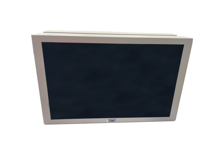
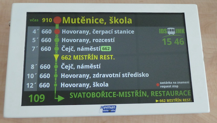
The VCS 379 E's internal side LCD panel.
LCD wiring for vehicle occupants
Indoor LCD vehicle panels are designed to save power during idle periods. To this end, the LCD panels have the following power management options:
- They can only be connected to the CS wire from the EPIS 4.0x on-board computer (power-up is thus controlled from the on-board computer). In this case, they must be switched on again approximately 80 seconds before the door is opened for passenger entry at the departure stop,
- They are connected to a permanent power supply and can be started from the PoE interface (our interface) or PoE, where the activation voltage is applied to the LCD (see description for EPIS 5 FCC).
- Use of the MSN (Minimize 24V Network) command, which is intended to minimize power consumption during times when nothing needs to be displayed, but it is advisable to keep the LCD panel on standby. By activating the MSN command sent from the on-board computer (e.g. EPIS 4.0x) over the Ethernet bus, the VCS type LCD panels can be switched to a reduced power state where their full function is not required, i.e. the LCD backlights are switched off while the control system - PC computer continues to operate (saving approx. 10W-30W per display).
The use of the MSN function is particularly advantageous in two modes:
- final, where during a short shutdown, only the LCD displays can be switched off while the PC LCD panel continues to operate and can be activated at any time (a long shutdown would be problematic),
- when recording vehicles, unless the LCD panel is connected to a separate power branch. Then there is no need to switch on the LCD itself when updating the data in the LCD.
Canceling the MSN state (minimizing power consumption) can only be done with a new MSN command - release - or by shutting down the system. When power is restored, the LCD panel will boot the system in the standard way.